
How to Install RC Servo Saver Correctly
03/08/2026
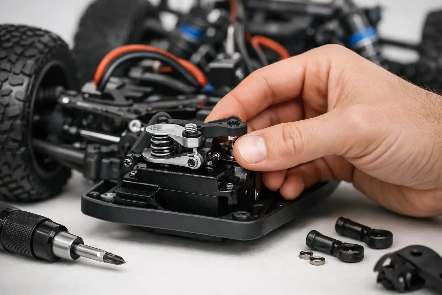
How to Install an RC Servo Saver: Step-by-Step Guide
A servo saver is a small steering component with an important job. It absorbs some of the force from impacts that would otherwise travel directly into the steering servo, helping protect the internal gears when a wheel catches a kerb, rock or rut.
Knowing how to install an RC servo saver correctly matters. A saver fitted one spline out, adjusted too tightly or left too loose can make an otherwise capable RC vehicle steer badly.
The job is straightforward on most RC cars, trucks and crawlers, but the order matters. Centre the servo electronically first, fit the saver in the correct position and then adjust the steering endpoints once everything is connected.
What Does an RC Servo Saver Do?
A standard servo horn is a solid arm attached directly to the servo’s output spline. A servo saver performs the same basic function but includes a spring-loaded or flexible mechanism.
When a wheel receives a hard impact, the saver allows a small amount of controlled movement instead of forcing the servo gears to absorb the entire shock.
This protection is particularly useful on:
-
Bashers
-
Monster trucks
-
Short-course trucks
-
Models driven over rough ground
-
Beginner RC vehicles
-
Crawlers fitted with large or heavy wheels
There is always a compromise. A softer servo saver provides greater protection but can make the steering feel vague. A firmer setting produces a more direct response but transfers more force into the servo and steering components.
Rock crawlers sometimes use firm servo savers or solid horns for precise steering. However, this places more responsibility on the servo, steering links and driver to withstand or avoid impacts.
Choosing the Correct Servo Saver
Before ordering a replacement, check that it matches the servo spline and the vehicle’s steering arrangement.
Common spline counts include:
-
23T
-
24T
-
25T
These fittings are not interchangeable. Many standard and aftermarket servos use a 25-tooth spline, but you should never assume this without checking the servo specification.
You also need to determine whether the vehicle uses:
-
A model-specific moulded servo saver
-
A servo horn with an integrated saver
-
A separate saver built into the steering bellcrank
-
A universal adjustable servo saver
-
A complete horn-and-linkage assembly
Some vehicles already have a servo saver elsewhere in the steering system. Fitting another one directly to the servo may introduce excessive movement and make the steering less precise.
If the original servo is being upgraded at the same time, browse our range of RC steering servos and check the spline, dimensions, torque, voltage and mounting arrangement before ordering.
What You Need Before Installation
Place the model on a clean workbench and support it securely with the wheels clear of the surface.
Depending on the vehicle, you may need:
-
The correct hex driver or screwdriver
-
A nut driver or socket
-
A ball-link tool
-
Small pliers
-
Side cutters if a cable tie must be replaced
-
A small amount of medium-strength threadlock
-
The vehicle manual or exploded diagram
Only use threadlock where the fixing is genuinely metal-to-metal and the manufacturer permits it. Do not apply threadlock to plastic threads because it can damage some plastics and make future servicing difficult.
Keep the original servo retaining screw safe. Do not replace it with a random screw, as one that is too long may bottom out inside the output shaft before properly securing the saver.
If the model has been driven outdoors, clean around the steering assembly before starting. Dirt trapped in the bellcranks, steering posts or rod ends can cause binding that may be mistaken for a servo-saver problem.
How to Install an RC Servo Saver
1. Centre the Radio System
Switch on the transmitter and set the steering trim and sub-trim to zero. Make sure any steering mixing is disabled unless the model requires it.
Switch on the receiver and allow the servo to move to its electronic centre position. Do not force the wheels while the servo is powered.
This is the stage most commonly skipped. If the replacement saver is fitted while the servo is off-centre, the vehicle may drive with the wheels pointing left or right even when the transmitter wheel is straight.
Once the servo has centred, switch off the vehicle and disconnect its battery. With a nitro model, switch off and disconnect the receiver battery and make sure the engine cannot start while you are working.
2. Remove the Existing Horn or Servo Saver
Access varies between models. On some RC cars, the servo saver is easy to reach from the top of the chassis. Other vehicles may require the removal of a receiver-box cover, top deck, bumper or steering brace.
Disconnect the steering link from the old horn or saver if necessary. A ball-link tool is the safest option because it removes the link without twisting or damaging the plastic rod end.
Remove the centre screw from the servo output shaft and carefully lift the horn or saver away from the spline. If it is tight, gently rock it from side to side. Avoid levering hard against the servo case.
Inspect the old component for:
-
Cracks around the spline
-
Rounded or stripped teeth
-
A damaged or weakened spring
-
Distorted plastic
-
Excessive movement in the pivot
-
Loose or damaged mounting hardware
If the old saver has failed following an impact, inspect the steering links, bellcranks and servo gears before fitting the replacement.
3. Assemble the Replacement Saver
Some servo savers arrive as a complete assembly. Others require the upper arm, lower arm, spring, collar and retaining hardware to be assembled before installation.
Follow the vehicle manual or copy the orientation of the original assembly. The output arm must face the correct direction so that the steering link lines up naturally without being pulled sideways.
If the saver has an adjustable spring collar, begin with the manufacturer’s recommended setting. If that information is unavailable, use a moderate initial setting and adjust it after testing.
Do not immediately tighten an adjustable saver fully. If the mechanism cannot move under a hard impact, it effectively becomes a solid servo horn and provides little protection.
4. Fit the Saver to the Centred Servo
With the vehicle switched off and the servo still in its centred position, place the replacement saver onto the output spline.
Position the arm as close as possible to its correct neutral angle. On many vehicles, the horn sits close to 90 degrees relative to the servo or steering linkage, but the correct position depends on the chassis design.
Fit the centre screw and tighten it securely without overtightening it. If the fixing enters a metal output shaft and the manufacturer allows it, apply only a very small amount of medium-strength threadlock to the screw. Keep threadlock away from plastic parts and bearings.
Reconnect the steering link and make sure the ball end is fully seated. The link should sit naturally without being forced sideways or placed under tension at neutral.
5. Check the Steering Mechanism
Before restoring power, inspect the steering assembly carefully.
Check that:
-
The servo saver clears the chassis.
-
The linkage does not catch on the receiver box or electronics.
-
Ball links are fully seated.
-
Turnbuckles are not bent.
-
Bellcranks move freely.
-
Wires cannot become trapped in the steering.
-
The wheels are approximately straight at neutral.
Do not repeatedly force the wheels from lock to lock by hand with the servo connected. Doing so can back-drive the servo and potentially damage its gears.
If the wheels are visibly off-centre, reposition the saver by one spline where possible. Use the adjustable steering link or turnbuckle for finer mechanical correction. Transmitter trim should only be used for a small final adjustment.
Set the Steering Endpoints
Reconnect the battery and switch on the transmitter before switching on the vehicle.
Support the chassis so the wheels are clear of the surface. Slowly turn the transmitter from the centre towards full left and full right while watching the linkage.
The servo should stop before the steering mechanism reaches a solid mechanical limit. Buzzing, straining or continued movement from the servo usually means it is trying to push the steering beyond its available travel.
Use the transmitter’s steering endpoint adjustment—sometimes called EPA, travel adjustment or ATV—to reduce the travel in each direction. Set the left and right endpoints separately if the radio supports it.
Correct endpoint adjustment is especially important after fitting an aftermarket high-torque servo, different steering knuckles or a servo saver with a different arm length.
Once the endpoints are set, place the vehicle on the ground and test the steering again. The wheels should respond smoothly and return close to centre without the servo buzzing.
How to Adjust Servo-Saver Tension
An adjustable servo saver should be firm enough to steer the vehicle properly but still able to absorb a sharp impact.
If the saver slips during ordinary steering:
-
Tighten the spring collar in small increments.
-
Check that the steering linkage moves freely.
-
Confirm that the servo has enough torque.
-
Look for worn or cracked parts.
If the saver does not move at all under a reasonable impact:
-
Reduce the spring tension slightly.
-
Check that the mechanism has not seized.
-
Confirm that it has been assembled correctly.
Do not deliberately stall the servo for long periods while testing. A stalled servo can draw considerable current, become hot and potentially damage itself or overload the ESC’s BEC.
Make one adjustment at a time and test the vehicle before tightening it further.
Common Servo-Saver Problems
The Wheels Are Off-Centre
First check that the steering trim and sub-trim are set to zero. Confirm that the servo was electronically centred before the saver was installed.
If the alignment is significantly wrong, remove the saver and reposition it on the spline. Use the steering linkage for fine mechanical adjustment and transmitter trim only for the final small correction.
The Vehicle Steers Further One Way
Unequal steering travel may be caused by:
-
Incorrectly set endpoints
-
An off-cententre servo saver
-
Unequal steering-link lengths
-
A bent steering component
-
The linkage contacting the chassis
-
Incorrect bellcrank assembly
Check the mechanical setup before assuming that the transmitter or servo is faulty.
The Steering Feels Vague
A loose saver spring can make the vehicle wander or respond slowly, but it is not the only possible cause.
Also inspect:
-
Ball links
-
Bellcrank bearings or bushes
-
Steering posts
-
Servo mounting screws
-
The servo output spline
-
Steering turnbuckles
-
Wheel bearings
-
Suspension components
Tightening the servo saver will not correct wear elsewhere in the steering system.
The Servo Buzzes or Gets Hot
A servo that continuously buzzes, chatters or becomes hot needs attention.
Check for:
-
Excessive steering endpoints
-
Binding at full lock
-
A seized bellcrank
-
Overtightened steering hardware
-
Damaged servo gears
-
Incorrect BEC voltage
-
Steering links catching during suspension movement
Check the linkage through its normal suspension movement, not only with the chassis sitting flat on the bench. Modified ride height and suspension geometry can cause steering links to bind as the suspension compresses.
Choose a Setup That Suits Your Driving
There is no single servo-saver setting that suits every RC vehicle.
A high-speed basher regularly landing jumps benefits from a saver that can absorb sharp impacts. A race car may need a firmer setting for consistent and precise steering. A crawler fitted with a powerful servo and heavy tyres needs enough stiffness to hold its line without placing unnecessary strain on the steering system.
After the first run, check:
-
The servo retaining screw
-
Steering-link hardware
-
Saver spring tension
-
Servo temperature
-
Steering endpoints
-
Whether the wheels still return to centre
A few minutes spent installing and adjusting the servo saver properly can prevent stripped servo gears, improve steering performance and keep your RC vehicle running for longer.
Frequently Asked Questions
Do all RC cars need a servo saver?
Not every RC car uses a servo saver directly on the servo. Some have one built into the steering bellcrank, while specialist racing or crawling setups may use a solid horn.
However, some form of impact protection is useful on most general-purpose and bashing vehicles.
How do I know which spline my servo uses?
Check the servo specifications, manufacturer’s instructions or the markings on the original horn. Common spline counts include 23T, 24T and 25T, but they cannot be used interchangeably.
Do not order a servo saver based on appearance alone.
How tight should an RC servo saver be?
It should be tight enough to steer accurately during normal driving but still able to give under a sharp impact.
Start with the manufacturer’s recommended setting and make small adjustments. Fully tightening the spring can remove the protection the saver is designed to provide.
Why is my steering off-centre after fitting a servo saver?
The saver may have been installed while the servo was not electronically centred, or it may be positioned incorrectly on the output spline.
Set the transmitter trim to zero, centre the servo and reposition the saver mechanically. Use trim only for a small final correction.
Why does my steering servo buzz at full lock?
The steering endpoint may be set too far, causing the servo to push against the vehicle’s mechanical steering limit.
Reduce the endpoint in that direction until the servo stops just before the linkage binds.
Can I use threadlock on a servo-saver screw?
Only use threadlock when the screw enters a metal thread and the manufacturer permits it. Apply a very small amount of medium-strength threadlock.
Do not use it on plastic threads, and keep it away from plastic components and bearings.
Is a solid servo horn better than a servo saver?
A solid horn can provide sharper and more precise steering, but it transfers impact forces directly into the servo gears and steering system.
It may suit certain racing or crawling applications, but a servo saver generally offers better protection for bashers and everyday RC vehicles.
Should I upgrade the servo when replacing the saver?
Not necessarily. Replace or upgrade the servo only if it is damaged, too weak for the vehicle or unsuitable for your setup.
If fitting a stronger servo, check its dimensions, spline count, torque, operating voltage and the ESC’s BEC output before buying.
Browse our complete range of RC servos.
Written by RC Model Shop
This article was written by the team at RC Model Shop, one of the UK’s leading specialists in hobby-grade radio-controlled vehicles.
With years of hands-on experience selling, repairing and upgrading RC cars, trucks and crawlers, we help customers choose compatible servos, servo savers, replacement parts and radio equipment. Our advice is based on practical experience working with hobby-grade RC vehicles rather than manufacturer specifications alone.
Whether you are repairing damaged steering, upgrading to a high-torque servo or setting up a new build, our goal is to help you choose the right components and install them correctly.
For expert advice or help finding a suitable servo or servo saver, contact the team at RC Model Shop or browse our range of RC servos online.